
Integrating Carbon Monoxide Transmitters with a BMS: 4-20mA, 0-10V and RS-485 Modbus RTU
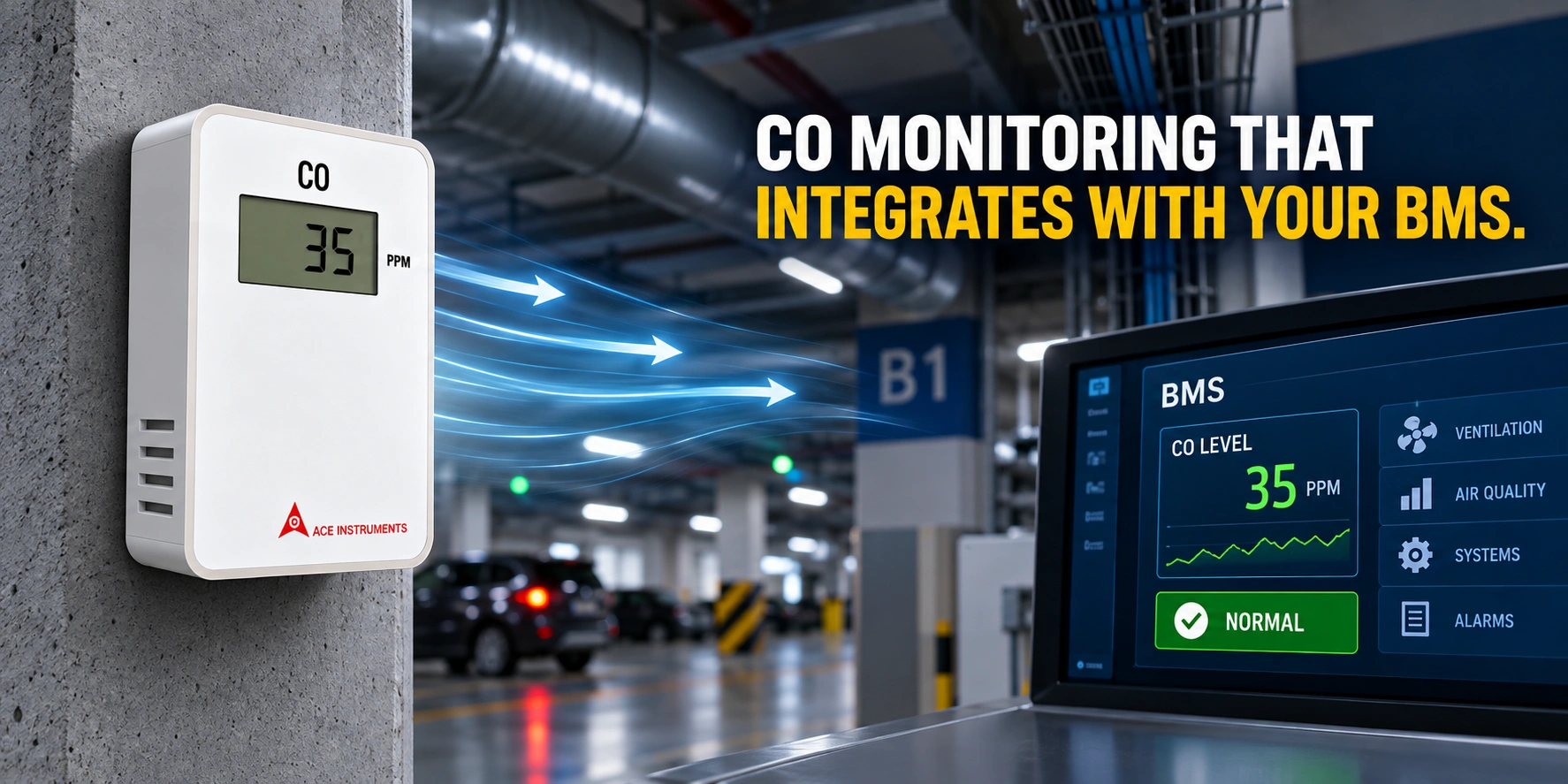
A carbon monoxide transmitter connects to a building management system by one of three routes: a 4-20mA current loop, a 0-10V voltage signal, or an RS-485 digital connection running Modbus RTU. The right choice is determined almost entirely by point count and cable topology, not by any general superiority of one method.
This is usually the last technical question before an order is placed, and getting it wrong is expensive in a way that is not obvious until installation. The wrong output on a fifty-point basement produces either a controller full of analogue input cards or a cable schedule nobody costs.
Output type selection
Why 4-20mA persists
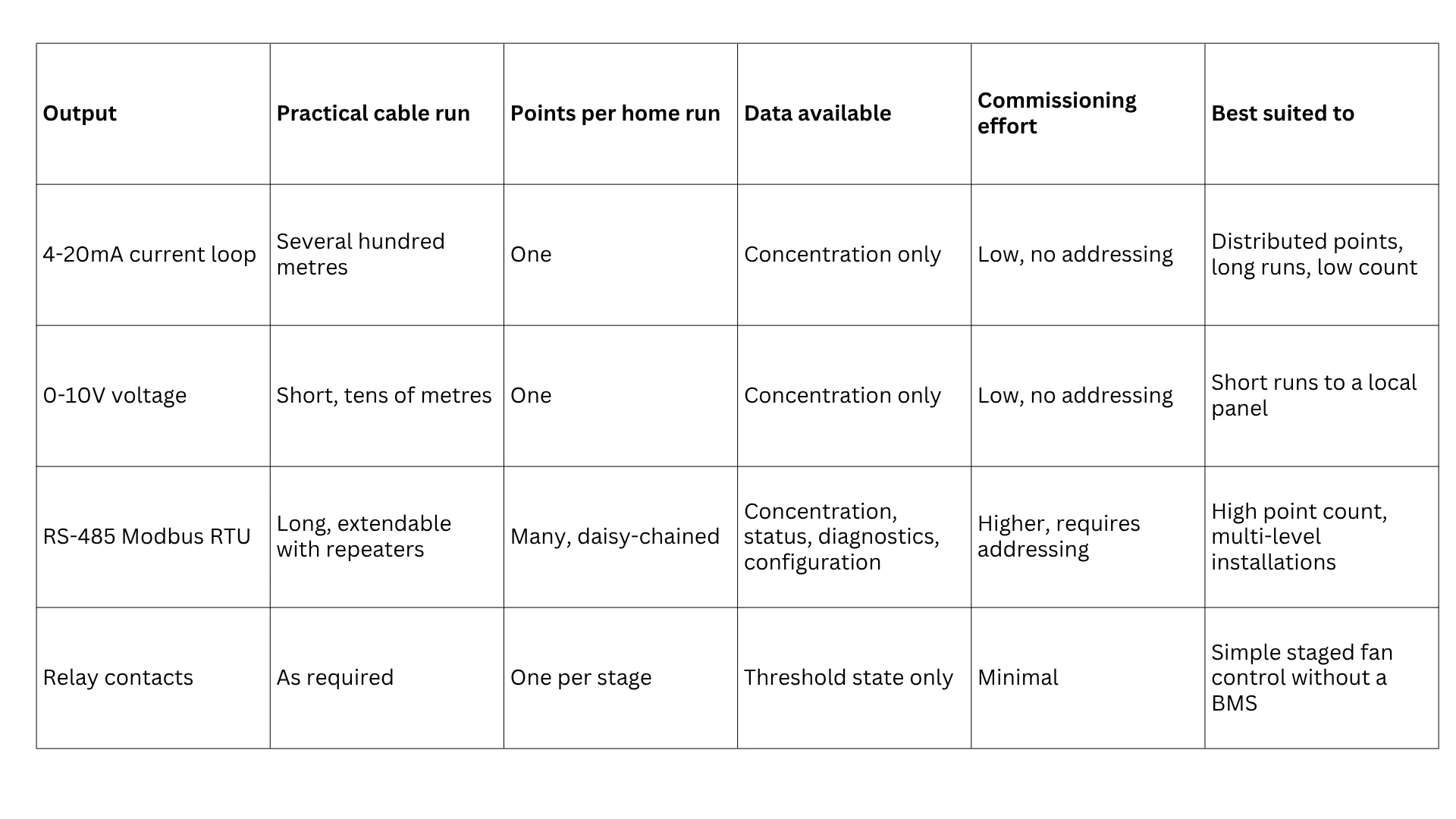
The 4-20mA current loop is old, and it remains the default for distributed field instrumentation for reasons that have not been superseded.
Current is constant along a conductor regardless of voltage drop. A 0-10V signal degrades progressively with cable length as resistance eats into the voltage, so a reading accurate at the panel is wrong at distance. A current loop is immune to this, which is why it tolerates the runs a car park or a large plant room imposes.
It also fails informatively. The live zero at 4mA means zero concentration reads 4mA, so a reading of 0mA is unambiguously a broken loop rather than clean air. That distinction matters in a safety-related system, where the most dangerous failure is one that looks like a good result.
The cost is topology. Each instrument needs its own conductor pair back to a controller input. On a small installation that is trivial. On a fifty-point basement it means fifty home runs and enough analogue input capacity to receive them.
Why 0-10V is the narrowest case
A 0-10V output is simple and widely accepted by HVAC controllers, and it is the right answer over short distances to a local panel. Over any significant run it is the wrong answer, for the voltage drop reason above, and it offers no live zero, so a failed instrument and a zero reading are indistinguishable. Specify 0-10V where the controller requires it and the run is short. Otherwise 4-20mA does the same job better.
Why RS-485 Modbus RTU wins on point count
RS-485 changes the topology rather than the signal. Instruments are daisy-chained on a single twisted pair, each with its own address, and the controller polls them in turn.
The effect on a multi-level car park is substantial. Instead of one home run per instrument, a single trunk serves a level or a zone, picking up instruments as it passes. Cable quantity, containment, controller input capacity and installation labour all fall together.
The second advantage is what travels on the wire. An analogue output carries one number. A Modbus connection carries the concentration plus whatever else the register map exposes: instrument status, fault flags, calibration state, and often configuration access. For a system whose credibility depends on instruments holding calibration, being able to read status remotely rather than by visiting each unit changes the maintenance economics, as discussed in the guidance on calibration and bump testing.
The cost is commissioning. Every device needs a unique address, the trunk needs correct termination, and the register map must be understood at both ends. This is a few hours of skilled work rather than a design risk, but it is not zero, and it needs to be in the programme.
A worked comparison
Consider a three-level basement car park with eighteen carbon monoxide monitoring points, six per level, controlled by a BMS at ground level.
With 4-20mA: eighteen home runs to the controller, each traversing up to three levels of containment, and eighteen analogue inputs, typically meaning additional input modules. Cable quantity is the dominant cost. No addressing work, and a fault on one loop affects only that point.
RS-485 Modbus RTU: three trunks, one per level, each daisy-chaining six instruments and running once to the controller. One serial port serves all eighteen points. Cable quantity falls by roughly an order of magnitude. Addressing and termination are required, and a break in a trunk affects everything downstream of it, which is why segment integrity and termination discipline matter.
At eighteen points the digital option is clearly better. At three points it would not be. The crossover sits somewhere in between and depends on the cable distances involved, which is why the decision should be made against the actual layout rather than a rule of thumb.
Integration for control, not just monitoring
Where carbon monoxide monitoring drives ventilation rather than merely reporting, the output must suit the control action.
Staged fan control needs either a proportional signal the controller can band, or relay contacts at each threshold. Relay outputs allow a system to work without a BMS at all, which suits smaller installations, but they discard the underlying value and cannot support the demand controlled operation described in ASHRAE 62.1-2022 and carbon monoxide.
Variable speed control needs a genuinely proportional signal, since the whole point is to modulate rather than switch. Both 4-20mA and Modbus serve this; relay contacts do not.
Fire mode override must sit outside the carbon monoxide logic entirely. Whatever the output type, the fire interface should be hard-wired and independent, so that no communication failure, address conflict or controller fault can prevent smoke extraction. This is set out in the basement car park design guide.
Getting the specification right
Four questions settle the output decision:
- How many points, and how far apart? This is the primary driver. High count over distance favours RS-485.
- What controller inputs are available? Existing spare analogue capacity may make 4-20mA the cheaper answer regardless of count.
- Is per-instrument diagnostic data needed? If maintenance visibility matters, Modbus is the only option that provides it.
- What must survive a communications failure? Fire mode and any critical alarm should not depend on the data path.
Mixed installations are legitimate. A large basement might use RS-485 for zone monitoring while a small number of critical points, such as a plant room or a duct-mounted unit interlocked to unit shutdown, use hard-wired analogue or relay outputs for independence.
Instruments and outputs
Ace Instruments supplies fixed carbon monoxide instrumentation under the IAQ Detectors brand with output options selected to suit the control system rather than the reverse. The AI-CO Carbon Monoxide Transmitter and duct-mounted AI-CO-D share the output conventions used across the wider range, so a project combining carbon monoxide with carbon dioxide, differential pressure or multi-parameter indoor air quality instruments can present a consistent integration approach to the BMS contractor rather than several different ones.
Ace Instruments has designed and manufactured indoor air quality instrumentation from its 10,000 sq ft Hyderabad facility since 1991, with more than 1,000 installations worldwide. The IAQ Detectors range is CE certified and manufactured under an ISO 9001:2015 registered quality system. The complete range is available in the carbon monoxide category.
Frequently asked questions
How do carbon monoxide transmitters connect to a building management system?
Carbon monoxide transmitters connect to a building management system by one of three output types: a 4-20mA analogue current loop, a 0-10V analogue voltage signal, or an RS-485 digital connection running Modbus RTU. Analogue outputs use one dedicated input per instrument at the controller. RS-485 allows many instruments to share a single daisy-chained cable, with each addressed individually.
Should I use 4-20mA or Modbus RTU for carbon monoxide monitoring?
Use 4-20mA for a small number of instruments over long cable runs where simplicity and fault transparency matter most. Use RS-485 Modbus RTU where the point count is high enough that dedicated controller inputs and home-run cabling become the dominant cost, typically on multi-level car parks. The decision is driven by point count and cable topology rather than by any inherent superiority of one output.
How many carbon monoxide transmitters can share one RS-485 trunk?
An RS-485 segment supports a substantial number of addressed devices on a single daisy-chained pair, with the practical limit set by the driver loading of the devices, cable length and baud rate rather than by a fixed count. Repeaters extend a segment where the device count or distance exceeds the limit. Confirm the supported device count for the specific instruments being used.
What is the maximum cable run for a 4-20mA carbon monoxide transmitter?
A 4-20mA current loop tolerates long cable runs, commonly several hundred metres, because current is unaffected by voltage drop along the conductor. The practical limit is set by the loop’s total resistance against the transmitter’s available compliance voltage. This immunity to voltage drop is the main reason 4-20mA remains preferred over 0-10V for distributed installations such as car parks.
Know the latest trends in IAQ solutions from the Ace Instruments team


Get inspired and learn more
Instruments that exceed your technical expectations
Comprehensive and customized IAQ solutions for all applications

